In order to comply with ASHRAE Standard 62.1 outdoor air requirements, it is common to pair a dedicated outdoor air system (DOAS) or energy recovery ventilator (ERV) unit with a variable refrigerant flow (VRF) system. This document describes how to integrate a RenewAire DOAS or ERV with Premium controls to the Mitsubishi VRF system using input/output (I/O) connections.
In an alternate configuration, the Mitsubishi system may turn the ERV on and off. In this case, the only connection is the on/off command. That scenario is not covered by this document.
Overview of Components
The RenewAire unit comes with a heat pump coil either integral to the unit (DOAS) or as a separate component of the ERV (HE+DX Coil Integrated System). A third option would be to have the coils supplied by others. The RenewAire coils have been designed in CORES according to specifications put forth by Mitsubishi to meet the needs of the VRF system.
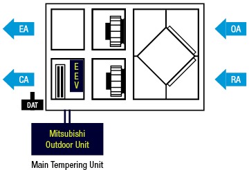
The RenewAire unit requires Premium Series Integrated Programmable Controls (IPC) for operation. RenewAire DOAS units will come with a discharge air temperature sensor (DAT). ERV units must supply the sensor separately (P/N: 131318). This sensor is required for control.
The Mitsubishi system may have one or two circuits with an option for hot gas reheat. Each circuit and/or coil requires its own linear expansion valve (LEV) kit, which are supplied through Mitsubishi. The DOAS units have room to mount the electric expansion valves (EEV) with the coil compartment, but the HE+DX coils do not. If using the latter, a separate box must be field-sourced. Contact RenewAire Technical Sales Support for additional information.
Control Type
In this scenario there are two types of control possible: Type 1, where the RenewAire system conveys the discharge air setpoint to the Mitsubishi system and the Mitsubishi system decides the capacity required to maintain the setpoint, and Type 2, where the RenewAire system decides the capacity and conveys that to the Mitsubishi system. It is suggested that Type 1 control is used as that is favored by Mitsubishi.
Minimum required for Type 1 control
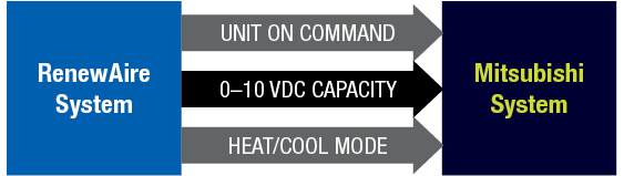
In order for the two systems to work, at minimum, the RenewAire system must send the following information:
Unit On Command
0–10 VDC discharge air setpoint or capacity, depending upon type
Whether the RenewAire system is in heating or cooling mode
Minimum required for Type 2 control
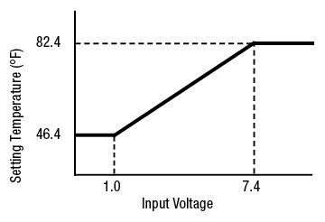
With Type 1 control, the 0–10 VDC signal is sent in the following manner as designated by Mitsubishi.
For Type 2 capacity control, the signal will correspond to 0–100% of capacity requested, which can be clipped with minimum and maximum output settings. For example, 3–9 VDC.
Input Voltage = 5.625 x SetP + 40.775[F]
Other optional information is as shown here at right.
The alarm input from the RenewAire system may not be required because the system will automatically turn the Mitsubishi unit off if there is an alarm.
The standard RenewAire system allows two binary inputs so there may be a limitation in the information coming from the Mitsubishi system. For example, if it is desired to have two inputs for defrost, the alarm signal could then be wired with the fan enable outputs, which will in turn shut the RenewAire unit off in alarm. This will be discussed further later in this document.
Sequence of Operations
When the RenewAire unit is turned on by the controller screen and BMS (if enabled), the OA and RA dampers will open, allowing the fan speed to be conveyed to the fans for operation. If the current switch for each fan does not detect operation, the unit will shut down on fan alarm. (It is possible to run the exhaust fan if the supply fan fails.)
Once running, the unit will determine which mode, heating or cooling, based on lockout temperatures. Stage(s) of compressor will engage based on settings and a tempering mode output will tell whether that is heating or cooling. A discharge temperature setpoint will output as a 0–10 VDC signal if Type 1 control is used, or a 0–10 VDC capacity signal if Type 2 control is used.
One or two digital inputs (depending on number of stages) may indicate the stage is in defrost. When in defrost, the fans will turn off. The staging outputs for any stage in defrost will stay active and any that are not in defrost will be inactive.
If either system is in alarm, neither system shall run.
In this section we will explain the field wiring and show the purpose of each connection. See the Wiring Diagrams PDF for complete wiring diagrams.
This document includes wiring for the RenewAire units with the colored DIN terminals as shown (for wiring to the older style grey terminal blocks, please contact RenewAire Technical Sales support).
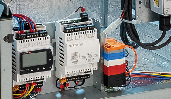
Wiring shown using colored DIN terminal blocks. In most cases, wiring will be direct to the controllers.
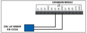
Wiring the Conditioned Air Sensor
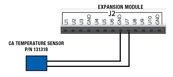
With DN units, the conditioned air sensor may already be wired into the unit. For ERV units, the sensor should be wired as follows.
Wiring directly to the expansion module terminals.
Wiring the 0–10 VDC Signal
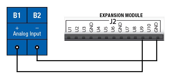
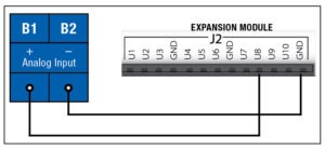
The wiring for the 0–10 VDC signal does not change based on whether Type 1 or Type 2 control is used. The RenewAire unit uses the cooling command output U9 on the expansion module and wires to the B1 and B2 analog input on each staging LEV kit. (Hot gas reheat uses a separate output.)
Wiring directly to the expansion module terminals.
Wiring the Tempering Mode
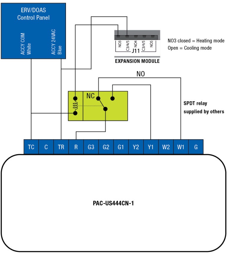
The tempering mode output from the RenewAire unit is a single dry contact output. Tempering mode is wired to the relay that in turn tells whether the unit is heating or cooling. The standard open output from RenewAire is open = heating, closed = cooling. An external relay is required. As shown in the picture, W1 should be closed for heating mode, Y1 should be closed for cooling mode. The Y1 output is also used for the HGRH enable, if used.
Mode input for each LEV kit—direct to expansion module.
Thermostat Connections and Interface Device
Connector
Purpose
Purpose
TC
Common (In)
To Transformer
C
Common (Out)
To Thermostat
TR
24VAC (In)
To Transformer
R
24VAC (Out)
To Thermostat
G3
Fan High
High Fan Speed
G2
Fan Medium
Medium Fan Speed
G1
Fan Low
Low Fan Speed
Y2
Y2
Stage 2 Cooling
Y1
Y1
Stage 1 Cooling
W2
W2
Stage 2 Heating
W1
W1
Stage 1 Heating
G
G
Fan
Wiring the Circuit Enable
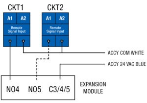
Each circuit requires an enable. The RenewAire system uses the cooling Stage 1 for LEV kit 1’s A1 and A2 terminals, and if a second circuit is used, it uses cooling Stage 2. These are dry contact outputs and are wired to provide 24VAC when active.
Wiring to Stage 1 (and Stage 2) LEV kit direct to expansion module.
Wiring the RenewAire Alarm Output to Mitsubishi (optional)
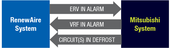
If the RenewAire unit is in alarm it will disable the VRF units by opening the contacts to A1 and A2. Additionally, the unit alarm may be sent to the Mitsubishi system if desired. In order for the VRF system to know if the RenewAire unit is in alarm, the main controller has a dry contact NO6 output that tells whether there is a major alarm and that can be wired in as shown, using the normally closed side to E1 and E2 on each LEV kit. (Do not use NO6 from the expansion module for this.) The wiring diagrams are shown at the end of the document.
Wiring the Defrost Inputs (optional)
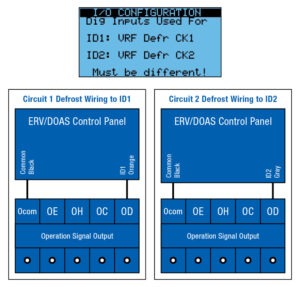
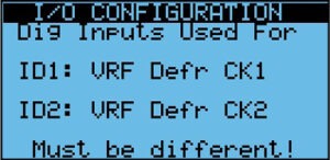
When either circuit is in defrost, the fans will shut down but the RenewAire system will hold the circuits in defrost ON. Any circuit that is not in defrost will be turned off. The wiring should coincide with the digital input setting as shown. These are dry contact inputs.
Defrost wiring circuit 1 for ID1 is wired to the orange terminal block instead of the jumper (bottom left). Defrost wiring circuit 2 for ID2 is wired to the grey terminal block (bottom right).
Wiring the Alarm Signal From Mitsubishi to RenewAire (optional)
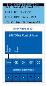
If there is an extra digital input available, it is advised to wire to the ID1 unit enable. The alarm signal will shut the unit off by opening the contact.
Error contact from Mitsubishi if wiring to ID1 as DI on/off.
If there is no open digital input the input can be wired in series with the supply air damper end switch. A fan alarm will occur in this instance.
Wiring the Hot Gas Reheat (optional)
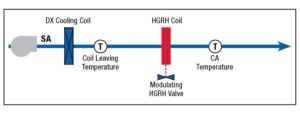
Mitsubishi recommends using a separate condensing unit for HGRH. To wire this, we use the U8 output of the controller in the B1/B2 analog input. and the cooling tempering to A1/A2. This feature also requires a coiling coil leaving air temperature sensor. DOAS units with factory-installed HGRH coils include this sensor. Other units will require an additional sensor. (P/N: 131318).
Hot gas reheat (HGRH)
Wiring of the cooling coil leaving temperature (LAT) directly to the expansion module
HGRH 0–10 VDC signal to the LEV kit for the HGRH direct from expansion module
Controller Settings
Unit Configuration
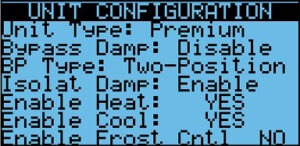
In Unit Configuration (password protected area), set the following settings:
Make sure the Enable Heat and Enable Cool are set to Yes.
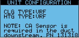
You can set the cooling and heating type here or the settings are also in the Control Settings.
Set cooling to VRF
Set heating to VRF or VRF & Mod if using auxiliary heat
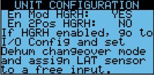
If you have HGRH, enable the modulating HGRH here.
I/O Configuration
Set the I/O configuration to match your application (password protected area):
In I/O Configuration, set the ID1 and ID2 to match the connected inputs.
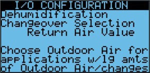
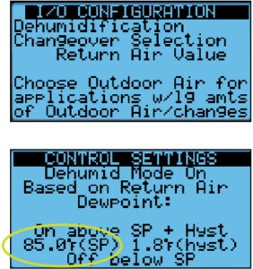
Enable the Dehumidification here if you desire to have a lower temperature for dehumidification. If you have HGRH, make sure you enable this selection. You can change over based on return air or outdoor air.
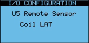
If you have HGRH, make sure the coil leaving temperature is set for Coil LAT on U5.
Other settings may be required if using the CO2 sensors, etc. Please consult the control manual for related information.
Control Settings
In Control Settings (after the fan settings), set the following settings:
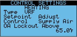
For the Heating selection, set:
Type VRF or VRF & Mod
Setpoint Adjust (via setting)
Control Supply Air
OA lockout temp for heating—set to OA temperature above which heating will be locked out
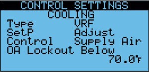
For the Cooling selection, set:
Type VRF
Setpoint Adjust (via setting)
Control Supply Air
OA lockout temp for cooling—set to OA temperature below which heating will be locked out
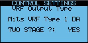
Set type of integration: Mitsubishi Type 1 or Standard Capacity, and select whether the unit will have one or two stages.
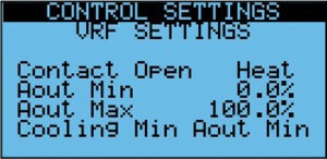
Select whether you want the tempering mode contact to be open for heat or for cool.
Leave the other settings as shown.
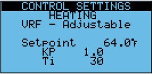
This is the discharge air setpoint for heating.
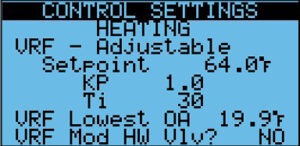
Kp and Ti are used to tune the heating control loop that is used for capacity control and also for two-stage heating.
If you have auxiliary heat, you will also have a setting for VRF lowest OA, which will be the temperature at which the auxiliary heat takes over. If the auxiliary heat is a 10–0V modulating hot water valve, the last setting should be Yes.
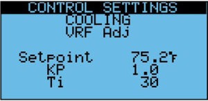
This is the discharge air setpoint for cooling.
Kp and Ti are used to tune the cooling control loop that is used for Capacity control and also for two-stage cooling.
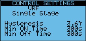
One-Stage Only
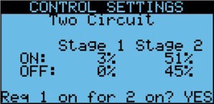
Two-Stage Only:
Based on demand, tell when each stage will turn on and off.
Is circuit 1 required for circuit 2 to run?
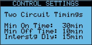
Two-Stage Only:
Minimum stage on/off and interstage delay.
Application Notes
Mode of Operation
For heating and cooling, the mode is determined by the outdoor air temperature.
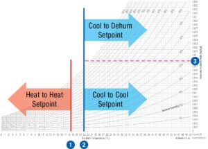
For dehumidification, the mode is determined by the outdoor air or return air dew point. The unit will only dehumidify if the outdoor air temperature is above the cooling lockout setpoint.
The order shown is the priority.
Heat Lockout OA Temp
Cool Lockout OA Temp
Dehumidification Changeover (Based on OA or RA)
Setting Staging Parameters
There are staging parameters depending upon whether the unit is one or two stages.
One Stage Parameters
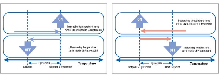
The main parameter is the hysteresis, which has the following effect on control.
Diagram illustrating hysteresis behavior in cooling (left) and heating (right).
Two Stage Parameters
The main parameters are the proportional band, Stage 1 on, and Stage 2 on, which has the following effect on control. Stage 1 goes off at setpoint. Stage 2 goes off at the Stage 1 on point. The off values may be adjusted in the I/O configuration.
Diagram illustrating parameters behavior in cooling (left) and heating (right).
Monitoring in Unit Status
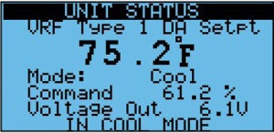
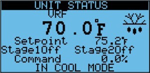
If using Type 1 control, the first screen will show the information for the 0–10 VDC output.
This screen shows the acting setpoint and staging information.
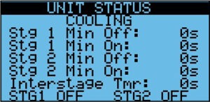
This screen will show any stages that are on or off due to timing. (E.g., if a stage is on due to minimum on time.)
Recent Case Studies
[loop_index]
Municipal: Prairie du Sac Town Hall
See how a town hall was retrofitted with a RenewAire ERV to meet ASHRAE Standard 241 and safeguard citizens from viral spread.